Latest Advances In LNG Compressors
05 September 2017
This article was originally published in the July issue of COMPRESSORtech2. We only publish a fraction of our magazine content online, so for more great content, get every issue in your inbox/mailbox and access to our digital archives with a free subscription.
By Antonio Pelagotti and Leonardo Baldassarre
Introduction
LNG production started in the 1960s with the plants in Algeria and Libya, then restarted in the ’80s and boomed in the last 10 years. Since the ’80s, we have seen fast growth of LNG production, starting from 3 metric tonnes per annum (mtpa) for Qatargas Liquefied Gas Co. Ltd. (QG) 1 and Woodside 1, to 7.8 mtpa for large QG projects. After that time, all the new plants have been designed around 5 mtpa. This paper will describe recent developments introduced in the latest LNG projects.
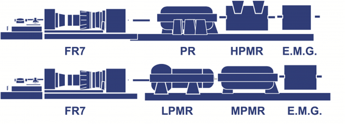
Previous and current train configurations: Recently, aeroderivative gas turbines such as the LM2500 or LM6000 have been used for 5 mtpa main refrigerant compressors, while in the past Frame 7s were used. A typical Frame 7 train’s installed power is around 190 MW just for the main refrigerant compressor. This type of train is installed in Egypt, Nigeria, Malaysia and Indonesia.
The same LNG production can be achieved with an LM2500, even though the process needs more equipment to reach the same installed power and LNG target production. So, to reach the same LNG output, a Frame 7 (Figure 1) needs two process drivers, an LM6000 (Figure 2) needs four and an LM2500 needs six. In the last case, the trains will operate in tandem to keep the production flowing even when one train is under maintenance.

Aeroderivative gas turbines as mechanical drives have been installed in Darwin, Australia, for the first time and now are in operation in Papua New Guinea, Australia and the U.S.

The typical compressor used in a large LNG plant is the beam-type centrifugal. For a specific service (low-pressure mixed refrigerant), a process axial compressor has been used. The main advantage of the axial compressor is its high efficiency and flexibility. Recently, big improvements have been made on adjustable guide vanes. The lifespan of the vanes has improved with maintenance schedules expected to match that of the driver.
The new LMS100 (Figure 3) is a driver that can be used in LNG thanks to its high flexibility and efficiency. The train can consist of the driver plus just two compressors to produce 4 mtpa of LNG.

It is worth noting that the longest refrigeration train in the world is installed in Angola and is configured as a Frame 7 and three centrifugal compressors plus an electric motor (Figure 4). This configuration has a second train (Frame 6 and three centrifugal compressors plus an electric motor) to complete the refrigeration loop. The entire liquefaction train comprises two trains using Frame 7s and two with Frame 6s for a production total of 5.2 mtpa.

The configuration of the Frame 7 with three compressors and an electric motor is very attractive because it can accommodate all the services (mixed refrigerant and propane) on the same shaft for a single liquefaction train. This can then be copied and the liquefaction plant can have a parallel train configuration, granting 365 days of production including maintenance of one driver. The helper motor can be designed to compensate for the gas turbine’s lack of power during the hottest days, granting full production during the year. A helper can also be used as a starter, reducing the gas flared during startup. This adds the disadvantage of complicating plant layout and complexity, but it is easily managed thanks to large engineering, procurement and construction (EPC) and oil company experience.
The most recent trend in LNG plant layout is to have multiple modules of equal capacity, with each module having one driver and one compressor with a single production variable from 0.6 to 1.5 mtpa, depending on driver power.

E-LNG has recently been used for a 5 mtpa plant in the U.S. The motor size is rather large at around 107,000 hp (80 MW). New, high-power gas turbines such as the LM6000PF+ and LM9000 (Figure 5) have been studied and deployed to maximize module capability. In these projects, there is only one process gas, typically a hydrocarbon mixture.
FLNG compressors
Several projects have been developed for floating liquefied natural gas (FLNG) applications with different liquefaction technologies. In FLNG applications, due to size and weight constraints, single-casing compressors are used, and these are often barrel designs for ease of installation and maintenance. Typical arrangements include a barrel compressor with an upward nozzle and optimized casing design to reduce weight and dimensions. Special tools must be developed to take care of bundle maintenance in offshore situations and must also take into consideration barge motion.
New Compressor Tech
High-pressure-ratio compressor development
Increasing financial pressures are causing a push for a reduction of the capital expenditures in the LNG market. A good way to limit costs is to reduce the volume of equipment installed and/or its size. Some original equipment manufacturers (OEMs) have recently introduced a high-pressure-ratio compressor (HPRC) to fulfill such a need. The main advantage of this equipment is related to the rotor construction, which is not made with a solid shaft piece with impellers assembled by interference fit, but is constructed by combining impellers connected axially with a geared connection (Hirth coupling) plus a tie rod. This design overcomes the speed limits for interference connections and increases the rotational speed of the impeller by approximately 40%. For a train equipped with an HPRC, the gear can be either a standard parallel axis-type design or an epicyclic gear to reach the highest gear ratio.
The impeller for an HPRC can be open- or closed-type, depending on mechanical properties and efficiency.
The HPRC allows approximately a:
- 50% footprint reduction.
- 30% reduction in weight.
- Higher reliability due to auxiliary equipment reduction (because of fewer casings).
- Lower downtime and easier maintenance.
Integrally geared compressors and isothermal compression
Centrifugal compressors used in the oil and gas world can be standard beam (between bearings) or integrally geared (IG) compressors. The main advantage of IG compressors is higher efficiency, because each impeller is working at its best efficiency point, increasing overall efficiency and reducing absorbed power. IG compressors can have coolers installed after each stage, which further improves efficiency.
Another major advantage of IG designs, especially important for LNG, is the higher operating range, as each stage can be fitted with inlet guide vanes (IGVs). In this way, overall efficiency can be maintained for alternate cases such as high ambient temperatures, resulting in higher annual production. This type of compressor can be used for a precooling service where compression can be optimized for each stream going through the machine and also on lower molecular weight services. A similar concept can be applied for standard beam compressors using cooled return channels and diaphragms, even though this complicates the overall arrangement of the compressor.
Liquid-tolerant compressor developments
Following the trend of cost reduction on capital items, new liquid-tolerant compressors (LTCs) have been developed in order to eliminate the use of or reduce the size of the scrubbers. The maximum amount of liquid carryover that standard centrifugal compressors can receive is about 2% of mass flow. Research and development goals are to develop an LTC that can tolerate liquid carryover up to 30% in mass (LMF) or 5% in volume flow (LVF).
This technology can be useful in booster gas compressors from the well to the liquefaction plant, and can reduce scrubbers within the liquefaction plant itself. Floating LNG applications can benefit even more with the elimination of large scrubbers.
Compressor design
Aerodynamics Impellers
Aerodynamics is the starting point of the compressors because it’s directly connected to the efficiency and the LNG production: a 1% increase in the compressor efficiency is equal to 1% increase in the LNG production for this kind of plant capacity. New aerodynamic solutions are always under development to increase the overall efficiency. State-of-the-art tools, tests and operating experience contribute to the design. For aerodynamics, the best tool is computational fluid dynamics (CFD). CFD is a relatively young science within the turbomachinery industrial world as it was only introduced at the beginning of the 1990s. Since then, much effort has been made to calibrate the tool and assess the level of accuracy of CFD, in order to better understand the amount of margin that needs to be applied within industrial applications. All OEMs need to dedicate a considerable amount of time to compare test results and CFD code results, benchmarking different types of soft- ware. It is commonly known that each type of software has multiple parameters that can be tuned in order to better fit the test results. After a good calibration, a new stage should be tested.
Scale model testing is very useful for performance estimation and validation of any computational tool. The geometry of the scale model test stage is reproduced and dynamic similarity is achieved as far as concerns flow coefficient, Mach and density ratio. The OEMs have developed good correlation to predict performance for the relative full-scale impeller. A model test is a limited-power-consumption test, and this limitation can raise concerns in terms of not being able to correctly identify the left limit (surge or stall of the stage). To avoid this limitation, the use of picocoulomb (PCB) probes is advisable. A PCB probe is able to make unsteady pressure measurements. If a mistake is made in the design of the compressor and the model test has resulted in a lack of performance — such as shortness of operating range (choke or stall) — or under performance, the stage will need to be redesigned in some part. All the measurements taken provide a good baseline from which to check when something goes wrong, allowing a quick redesign of the compressor that goes in parallel with the manufacturing of a new impeller. Within one month’s time, a new and optimized impeller can be tested. Scale model testing is a low-cost, low-time, effective way to anticipate performance.
OEMs have developed rules and analyses to predict the impact of geometrical scaling on performance with no surprises during the full-load test. For LNG, the most critical stages are within the pre-cooling compressor as we have the combination of low temperature with high molecular weight and large volume flows that make for a high Mach number.
Continuous cost reduction in the oil and gas market has obliged OEMs to optimize the rotating equipment, for example by reducing machinery size. This leads to the reduction of the impeller exit diameter and an increase of flow coefficient. Traditional, pure centrifugal stages start suffering from poor efficiency and range when the flow coefficient exceeds about 0.12, even though some have produced stages up to flow coefficient 0.18. To improve efficiency and range for flow coefficient range (0.12:0.24) and relative Mach number range (0.8:1.05), an optimized family of stages has been developed. Performance characterization up to a Mach number of 1.05 was considered following the demonstration by Grimaldi, et al. (2007) that reasonable performance could still be achieved even with such a high Mach level.
This development was done following a three-step approach:
1. Reviewed all internal test data and correlation of performance decay of pure centrifugal stages with “simple” geometrical parameters (specific impeller curvature, hub to shroud blade length ratio).
2. Identical activity was done comparing CFD RANS (Reynolds Averaged Navier Stokes) predictions with test data.
3. A base design respecting all criteria identified in step 1 was constructed and only local CFD optimization was performed.

A validation test plan was developed, and the comparison between global performance parameters expected from CFD and the early test results showed excellent agreement. Noticeable improvements of range, efficiency and head were visible. Figure 6 compares efficiency obtained by the five tested stages plus an additional test performed on a lower flow coefficient impeller. The new design proved to be aligned with existing stages at a flow coefficient lower than 0.1 and more efficient at high flow coefficient.
Seals: Compressor efficiency can also be increased by minimizing internal linkages. Standard stationary labyrinths, in aluminum or steel material, are not effective to achieve this target, since their designs have to take into account multiple aspects, such as operating conditions or rotordynamic behavior, that affect the seal gap sizing.
As an alternative solution, abradable seals can be used (Figure 7). They consist of an integral rotating labyrinth that works against a statoric insert arranged into the diaphragm. Abradable seals don’t suffer the issues mentioned above for stationary labyrinths. An abradable coating allows for tighter clearances compared with traditional aluminum seals, and prevents the possibility of rotor damage in case of abnormal vibrations. This solution is easier to maintain because the inserts can be renewed by recoating the abradable material.


Vaned: A further option to increase the efficiency is to use vaned parts. Vanes can be introduced upstream of the impeller blades — inlet guide vanes — or downstream in the diffuser. Here, there are multiple choices, including a wedge diffuser (typical for IG compressors), low solidity diffuser (LSD) or rib diffuser.
The IGV is a good solution because it is able to straighten the large distortion coming from the volute, increasing the efficiency of the downstream impeller.
A vaned diffuser can increase the efficiency at average operating conditions, but can lower it for alternate cases. For LNG service, the operating point moves along the curve during a 24-hour period, so a good average efficiency is preferred.
Unfortunately, IGVs are a source of aerodynamic wakes that hit the impeller blades. In case of coincidence of frequency between IGV wakes and impeller natural frequencies, the impeller can break.
Side streams: Refrigeration compressors are typically equipped with injections between one stage and another to keep all the service within one casing, which complicates the stage-by-stage performance prediction [12]. The same considerations for CFD design and model test validation can be applied to the statoric parts. OEMs have developed aerodynamic design practices to predict the impact of the shape of the injection stream onto the main stream. All major OEMs have validated side stream prediction rules with model tests performed both on test rigs or wind tunnels that have then been confirmed by full-scale tests.
However, real operating conditions may widely vary from design conditions for multiple reasons such as allowances on heat transfer equipment, calculated pipe diameters or equipment (pumps, vessels, etc.); favorable compressor performance relative to quoted polytropic efficiency; API margin; vendor margin; allowances on available turbine power; or any licensor allowances.
All the earlier considerations plus all the process and ambient variables make for operating conditions much different from the original design and reduce the real impact of the side-stream performance on the real compressor operation.
Mechanical design
Casing: LNG compressors can be horizontally or vertically split. The main advantages of the horizontally split compressor is maintenance capability (compressor arrange between driver and another equipment) and larger volume flows. The inlet volume flow can reach 176,000 cfm (300,000 m3/hr) and require a 70 in (1.8 m) flange.
Compressor layout also impacts the downstream gas path, which should be studied in order to accommodate a smaller compressor inner diameter to minimize machinery dimensions and weight, without impacting overall bearing span. By reducing the size of the compressor, it is possible to increase the maximum allowable working pressure (MAWP), which can improve the plant layout and overall plant operation.
A new design adopts a bolted end-cover solution, similar to the barrel- type concept. This allows a step increase in design pressure. A recent project in Australia, characterized by an internal compressor casing diameter of 118 in. (3 m) and a design pressure greater than 580 psig (40 barg) has been successfully tested. An interesting collateral advantage provided by the new casing design is the reduction of rotor-bearing span, with consequent benefits on the lateral behavior and stability of the compressor. Reduced bearing span and higher design pressure can lead to future developments to boost profitability by reducing the number of casings and, therefore, capital expenditures.
The compressor casing must be compliant to API and ASME requirements, avoiding multiple design pressures and additional O-rings on the horizontal flange to meet the design pressure. O-rings have a limited life (five to 10 years) and need to be replaced from time to time, reducing machinery availability. Moreover, it cannot represent a definitive solution, because gas can bypass the O-ring and leak outside.
Compressor walls and flanges must be thick enough to grant a safe operation over the years, compensating for transient or out-of-design operation at the job site. The best way to measure casings is to use finite element (FE) tools that should be validated by each OEM. The worst condition to be analyzed is the hydro test pressure, which is 1.5 x MAWP. In order to further optimize the casing, a thermal transient analysis can be performed to determine the effect of operating temperature on the casing assembly.
Impeller: The Impeller can take advantage of new tools such as FE to improve its robustness, keep the peripheral speed limit at a reasonable value (984 fps [300 m/s]), reduce the weight and increase the torque transmission. Every new stage design starts with the aerodynamic path, but once it’s established, the optimum mechanical dressing can be achieved by the use of optimization tools and design of experiment analysis by modifying cover shapes.
Rotordynamic
Lateral: The most important advance in rotordynamics is the ability to measure the logarithmic decrement of the compressors by the use of a magnetic exciter installed at one end of the compressor. In main LNG compressors trains, typically both ends of the compressor are connected to other rotating equipment (electric motor or centrifugal compressor), so the logarithmic decrement measurement with the exciter is not possible during a full load test. A stability test must be accomplished during a performance test or a mechanical running test at reduced power on the effectiveness of the test.
Torsional: The most used technology for the helper/starter electric motor is the load-commutated inverter (LCI). This technology introduces a torque ripple in the shaft line that can lead to the failure of the coupling. In addition, the greater the size of the electric motor, the stronger the torque ripple. The torque ripple issue can be managed during a string test by instrumenting the coupling and measuring the torsional behavior. The electric motor parameters can then be tuned to minimize the impact of the torque ripple in the train.
Operating experience for rebundle
Some LNG plants have operated for 10 or more years, and some operational analysis can be done to evaluate and rebundle to maximize production. For example, equipment designed at the time may suffer low efficiency due to a technology gap. New high-Mach, high-efficiency stages have been designed to improve performance without impacting stage axial dimensions. In this way, new stages can be installed in the same casing, increasing the overall efficiency of the machine.
The development of new high-Mach stages now can offer more than four points of efficiency with respect to the old. A possible rebundle for a propane compressor can increase the efficiency from an average of 72 to 80% at roughly 10% lower power.
In another plant, a previous debottleneck of the plant brought the compressor to work beyond the choke limit in a region that potentially could be detrimental for the compressor. New stages with larger operating ranges can be installed to cover high flow points, extending the actual operating range.
Auxiliary services
LNG plants are equipped with several auxiliary services that accompany compressor trains. These services are needed to increase plant efficiency (boil-off gas [BOG], end flash) or are necessary to keep the gas flowing (feed gas, domestic gas, stabilizer) or for fuel gas.
BOG compressor: Among all the auxiliaries services, the BOG compressor is one of the most critical. The BOG service recovers gas from the tank, avoiding flaring. A typical BOG train consists of a fixed-speed electric motor, a gearbox and a couple of centrifugal compressors to pressurize gas from almost ambient pressure to fuel-gas pressure for a gas turbine. The critical aspect of a BOG compressor is the temperature.

The minimum design metal temperature is typically -256°F (-160°C), which is also the suction temperature of the compressor; moreover, the compressor must work in an alternate case at around -184°F (-120°C) and at other conditions at ambient temperature (during recycle or at startup). This multiple-temperature operating condition makes the compressor difficult to design from a mechanical point of view, from the IGV movement in a cryogenic environment to transient operation to dry-gas seal insulation. The only material suitable at such low temperatures is 9% nickel. A qualification test campaign was developed and performed to verify the behavior of the material at different temperatures, avoiding issues of different relative displacement among components.
An OEM built a dedicated test model for IGV and insulation systems at low ambient temperatures (Figure 9). A scale 1:1 model was built and inserted in a tank that can be filled with liquid nitrogen at -310°F (-190°C). A detailed test sequence then verified the proper functioning of the system at different temperatures with aerodynamic load simulations on the IGV blades. The same tank has also been used to test an insulation system for the DGS with synthetic oil.
For other components, such as the rotor and diaphragm, where testing was not possible, an intensive finite element method campaign was performed to simulate transient behavior of the rotor and stator, checking relative movement and clearances.
All these studies were later applied to a BOG service for Qatar. In this case, three compressors were built, each one equipped with an IGV to compress gas up to Frame 9 fuel-gas pressure, and these have been in operation since 2014.
CO2 compressor: More recent protocols regulation will lead oil and gas companies to reduce CO2 emissions. Many of them have decided to re-inject CO2 in geological formations (Figure 10). In LNG, CO2 can be in the extracted gas and must be separated from the other components before liquefaction. For this reason, the CO2 is not pure as in a petrochemical plant, but it is mixed with water or hydrogen sulfide (H2S) that makes it an acid gas application. Even if there is still a large debate on which technology should be applied in CO2 applications, in case of high-pressure acid gas, the best choice for the moment is still a beam compressor versus an integrally geared compressor.

An example of a CO2 re-injection service is in operation in Australia where the service will be accomplished by two barrel compressors as described in detail in the paper “CO2 Compression at World’s Largest Carbon Dioxide Injection Plant,” presented at Turbo Symposium 2012 [15].
Other compressors: All the other compressors are more or less standard compressors. There are services that deal with clean natural gas, such as fuel gas, feed gas or booster gas, that usually use midsize barrel compressors driven by gas turbines at 33,000 to 40,000 hp (25 to 30 MW).
Dynamic simulations

Dynamic simulation is relatively new for the oil and gas business. It has increased its importance for multiple applications, such as startup; emergency shutdown; anti-surge valve verification; and process control software validation, debug and tuning (anti-surge, load sharing, performance controller) (Figure 11).
The startup simulation is extremely important for helper motor sizing and to increase the startup pressure of the compressor. Instead of depressurizing the loop completely, a higher pressure can be determined with good savings for refrigerator gas.
Modularization
As several LNG liquefaction plants are being built in remote areas where labor is very scarce and expensive, there is a trend towards modularization where a majority of the work can be done by the compressor OEM or in a separate module yard. The extent of modularization has to be an economic decision depending on the labor availability and other economic factors. The extent of modularization ranges from partially assembled units to full large-scale modules.
A fully modularized LNG plant can also be remotely controlled and implement new digital solutions that can optimize various equipment and boost LNG production.
Conclusion
Many innovative considerations and solutions have been presented, from new aerodynamics for impellers to new mechanical arrangements for impellers and casings; robust solutions for new projects and for rebundle have been also presented in addition to innovative solutions for auxiliary compressors. All considerations may lead to laying the foundation for the next generation of centrifugal compressors in the LNG market.
About the authors:
Antonio Pelagotti is manager of new product development within the Compressor Design Department for Baker Hughes, a GE company in Florence, Italy. Contact him at: [email protected]. Leonardo Baldassarre is the engineering leader for compressors, expanders, transmissions and electrical systems within Baker Hughes, a GE company in Florence, Italy. Contact him at: [email protected].
STAY CONNECTED

Receive the information you need when you need it through our world-leading magazines, newsletters and daily briefings.
POWER SOURCING GUIDE
The trusted reference and buyer’s guide for 83 years
The original “desktop search engine,” guiding nearly 10,000 users in more than 90 countries it is the primary reference for specifications and details on all the components that go into engine systems.
Visit Now
CONNECT WITH THE TEAM