Thermal Design Considerations For Centrifugal Compressor Piping Systems
19 October 2017
This article was originally published in the Aug./Sept. issue of COMPRESSORtech2. We only publish a fraction of our magazine content online, so for more great content, get every issue in your inbox/mailbox and access to our digital archives with a free subscription.
By Francisco Fierro, Angel Rivera and Benjamin White
Synopsis
Centrifugal compressor packages have become more popular for natural gas transmission applications in recent years as they are well suited to the necessary flow rate and pressure ratio requirements. Additionally, unlike reciprocating compressors, centrifugal compressors do not have the need for expensive pulsation bottles.
However, because the piping is connected directly to the compressor, a thermal analysis is vital to ensure compressor nozzle loads remain below the manufacturer’s specified limits. Exceeding these limits without approval from the manufacturer can lead to misalignment between the driver and compressor and can lead to coupling or bearing failures.
A proper thermal analysis should review and ensure a number of parameters are acceptable for operation. These include stress in the piping, compressor nozzle loads, cooler nozzle loads and pipe support reaction loads. Additionally, all mechanical natural frequencies should be identified, and design should reduce the likelihood of vibration problems.
Southwest Research Institute (SwRI) has performed many of these analyses and has identified common mistakes in centrifugal compressor piping layouts. These mistakes and resolutions will be presented along with general recommendations and good design practices. Following the provided information should result in a more robust design and will allow the piping designer to begin with a better initial design and account for possible problems in the design stage where changes and modifications are easily implemented.
Introduction
Centrifugal compressors have gained more popularity for natural gas transmission applications. This can be attributed to a variety of factors, such as lower emissions, cost considerations, no significant compressor-generated pulsation and a flexible range of operating conditions.
However, centrifugal compressors are much more sensitive to the thermal growth of the attached piping. The added loads on the compressor nozzles may affect the alignment of the compressor enough that API 617 has an allowable load limit. Along with nozzle loads, equipment loads are also affected by thermal growth, which is the case with cooler nozzles, for example. Additionally, if not properly designed, the piping layout of the station may have high-stress sections due to thermal growth.
Thermal analysis/design considerations
Larger diameter piping stiffness
Recent industry trends have led to the use of larger compressors and larger-diameter piping. This allows for higher flow rates and a lower number of units. Larger-diameter piping generally provides more stiffness than smaller piping. This is also apparent in elbows, which are often used to provide a flexible point and allow the pipe to grow thermally.
A model was developed which was composed of a 6 ft. (1.8 m) vertical run followed by a 6 ft. (1.8 m) horizontal run. The start point and end points remained the same, but the elbow and line size between the two end points were varied between 4 and 48 in. (100 and 1220 mm). This model would be representative of taking a cooler riser design used on a smaller line and using the same design on a much larger line size.
Figure 1 presents the stiffness of a typical piping run for different pipe size. The stiffness of the curve reveals that the piping stiffness increases exponentially. Because of this trend, a similar piping layout can result in much higher reaction loads and thermal stress. Elbows are often used to relieve thermal stress, and it is critical to review the change in thermal stress when increasing the pipe diameter.

Piping elbows
Oftentimes, the type of elbow used is determined by the station layout and the desired accessibility of certain areas to personnel. While 90° elbows are far more common than 45° bends, changing from one type of elbow to another can have significant thermal effects. Along with providing a lower pressure loss, 45° bends tend to provide a higher resistance to bending. Thermally speaking, additional stiffness in the piping run will usually lead to higher reaction loads at clamps and nozzles, as well as higher stress levels in the pipe. Figure 2 shows a comparison of a piping run with a 45° bend and a 90° elbow.

It is clear the 45° elbow nearly doubles the axial stiffness, which would lead to nearly doubling the loads and stresses in the area. Inversely, if a 45° elbow is installed and nozzle loads are excessive, replacing the elbow with a 90° bend will reduce the loads by the same stiffness ratio.
Compressor nozzle loads (API 617)
The piping, restraints and soil stiffness have a direct relationship to the stress in the pipe as well as the loads on the compressor nozzle. If the nearby restraints are rigid, the piping grows thermally towards the compressor and increases the nozzle loads. A very flexible system would result in low compressor nozzle loads, but would be very susceptible to vibration. This balance between thermal flexibility and mechanical stiffness is a critical factor that should be accounted for in a station piping design.

API 617 is commonly used to determine acceptability of the compressor nozzle loads on centrifugal compressors. The API 617 allowable values are equal to 1.85 * NEMA SM23. Nine different allowable values are calculated based on the “equivalent” nozzle diameter. An allowable multiplier is typically applied (often 3.0 * API 617). The calculated moments are resolved about a common point, which can and does affect the acceptability of the predicted loads. The summation of forces and moments are compared to the code allowable values along with the three combined loads shown below.
Individual Nozzle Loads
• Suction Flange 3 * Fr + Mr
• Discharge Flange 3 * Fr + Mr
Nozzle Load Summations
• SFx, SFy, SFz, SMx, SMy, SMz (six different allowable values)
• 2 * Fc + Mc
Figure 3 presents a sample calculation of the API 617 compressor nozzle allowable values.
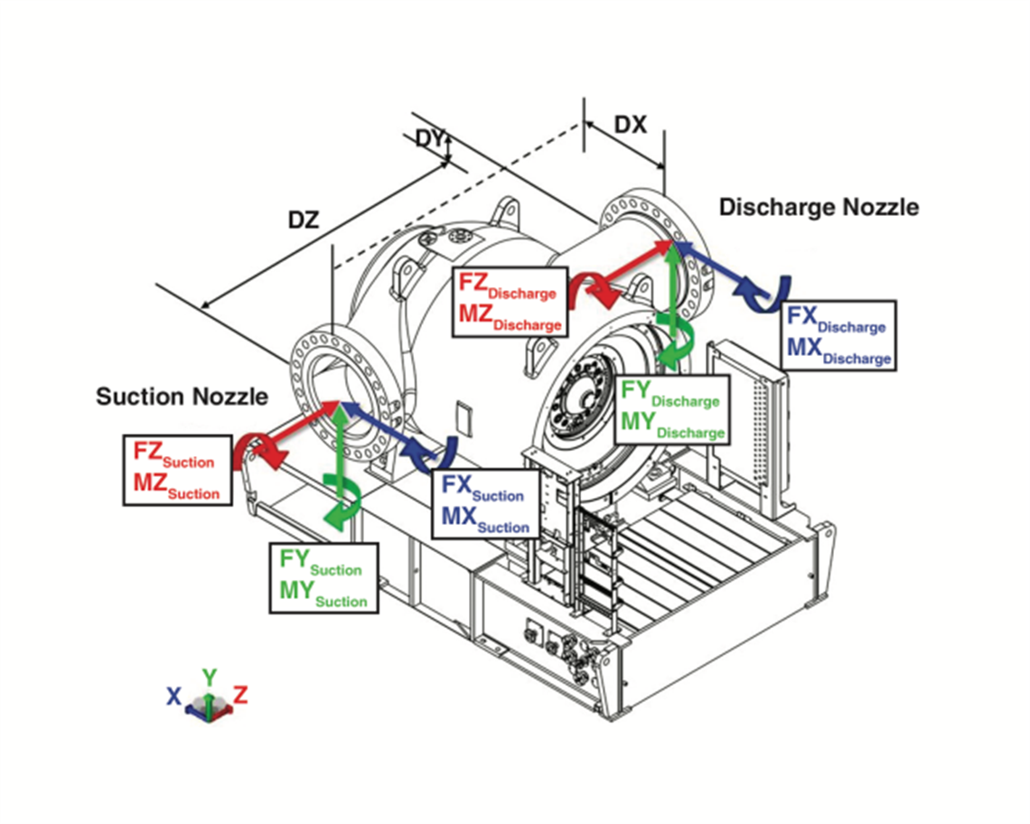
Oftentimes, resolving the loads about a single point will result in the highest value. This can be due to high thermal loads that should be lowered to ensure safe operation. For larger diameter piping, however, resolving the load about the discharge nozzle often results in a large moment about the X-axis as shown in Figure 4. The weight of the suction flange (FY) is multiplied by the length between the compressor nozzles (DZ) and creates a high moment about the discharge nozzle. This is not due to any thermal growth of the piping or unit; it is due to the weight of the flange.
The predicted loads and code check should be discussed with the original equipment manufacturer (OEM) to determine if the loads are acceptable to the vendor. A good understanding of the loads and their sources is necessary to understand whether the loads are due to a thermal growth issue or if it is a result of the resolved loads calculation. Good design practice can often lower nozzle loads to acceptable levels during the design phase and is preferred to validating high loads and having a review by the OEM.

As discussed later in this paper, improper modeling techniques and temperature range selection can lead to underpredicting equipment loads. At a new compressor station, large diameter piping (36 in. [915 mm] suction, 30 in. [762 mm] discharge) and the compressor were analyzed during the design phase of the project.
The goal of this analysis was to evaluate various pipe routing and ensure that equipment loads were within acceptable limits. In this case, using 45° elbows on the suction piping was preferred (in order to keep the centerline of the compressor as low to the ground as possible). A thermal stress analysis was performed during the design phase and this pipe routing (and the predicted equipment loads) was deemed acceptable.
During the commissioning of the compressor package, several issues were noted with the piping. A new piping thermal model was independently built and followed the modeling techniques cited herein. These results showed equipment loads in excess of allowable API values and much closer to those limits established by the OEM. Using this updated model, design changes were identified that would lower the stresses in the piping as well as lower the predicted equipment loads. These costly changes were then implemented with much better results.
Cooler riser design considerations
A key design factor when developing a piping layout is maintaining acceptable cooler nozzle loads. The cooler manufacturer will, in most cases, provide maximum allowable loads for the attached piping. If overly restrained, the thermal growth of the pipe will impart large loads on the cooler nozzles. This section of piping usually requires much higher flexibility than other sections of piping. Excessive flexibility can also increase the nozzle loads, as the weight of the pipe would then be supported by the cooler. As discussed earlier, larger-diameter piping provides significantly higher stiffness and a similar layout, which is acceptable for smaller piping and may result in excessive loads with a larger diameter line.
Figure 6 presents a common cooler riser design on a natural gas compressor station in the design phase. A 20 in. (508 mm) line splits at a tee, turns vertical and reduces down to 14 in. (356 mm) at the nozzle connection. This configuration resulted in a maximum load in the vertical direction of 102% of the allowable and 127% in the cooler lengthwise direction.
The vertical load is due to the thermal growth of the vertical run into the cooler. A pipe support near the tee forces the piping to grow upward towards the cooler nozzles. Additionally, the horizontal run between the buried header and tee cannot grow away from the cooler as the piping is buried just upstream of the elbow, and therefore grows towards the cooler.


The thermal growth is dependent on the operating conditions and the length of each run. While the operating conditions cannot typically be changed, the length of the piping runs can be modified by rerouting the piping. This would reduce the amount of thermal growth, but is not always preferred. The final option is to adjust the stiffness in the area by adjusting pipe clamp locations, line size, elbow types, etc.


The final recommended system in this case involved shifting the pipe support away from the cooler to allow the vertical pipe run to grow downward and lowering the reducer from the top of the vertical run to the bottom. Shifting the reducer increases the bending flexibility of the vertical run and lowers the horizontal load on the nozzle. As shown in Figure 7, the vertical and horizontal loads were reduced to 80 and 73% of the manufacturer allowable loads.


Modeling techniques
Clamp modeling
After all the piping design factors have been considered and all criteria have been met, there is still the possibility the final design will fail and the thermal analysis results are invalid. This can be due to the modeling techniques used in the analysis. For mechanical piping reviews and general piping design, a pipe clamp is generally considered a fixed point.
While a full strap-type clamp as shown in Figure 8 does provide a stiff support, it cannot be considered rigid. Every clamp and clamp type have a translational and rotational stiffness associated with the clamp. U-bolt type pipe supports are much more flexible than a strap type clamp and provide low rotation stiffness. If the appropriate clamp stiffness is not considered in the model, the thermal growth, pipe stress and resultant nozzle loads are not accurate.
Additionally, a reaction load is calculated at each clamp location. These loads are a result of the thermal growth and the clamp stiffness. High clamp stiffness will result in unrealistic high reaction loads. High stiffness will also act a fixed point and reduce the amount of thermal growth at the compressor or cooler nozzle. For accurate modeling predictions, it is essential to accurately estimate stiffness in all directions.

Nozzle modeling
Similarly, the stiffness used in the connection between the piping and the compressor or cooler nozzle will have a significant impact on the resultant nozzle loads. A fraction of an inch in deflection of the piping can produce thousands of pounds of force on the nozzle if the connection stiffness is unreasonably high. The appropriate stiffness, which accounts for the equipment geometry, wall thickness and support, must be used. If the stiffness is not accurate, the resultant loads and the equipment nozzle checks are not valid. The equipment stiffness values can be determined through experimental testing or through finite element modeling of the equipment.
Temperature cases
When performing a thermal analysis, it is important to analyze all the expected operating conditions. According to 832.3f of ASME B31.8 Gas Transmission and Piping Systems [1], “The total range in temperature shall be considered in all expansion calculations.” This includes the hottest design case as well as the lowest cold case. Oftentimes, this can be during a shutdown of the compressor in the middle of winter. The attached piping and equipment will contract, imparting loads on all the clamps and equipment nozzles. It is important to ensure this contraction will not result in excessive loads or stress in the pipe.
Conclusions
Thermal analyses are critical to ensure the proposed piping layout is acceptable. A previous acceptable station design may yield different results when applied to a different location with new operating conditions, line sizes, elbows, etc. These changes can have significant effects on the predicted resultant stress and loads. Applying poor modeling techniques or improperly defining the temperature ranges of the thermal analysis model may lead to erroneously approving an inadequate design if maintenance is not taken to model the configuration accurately and/or conservatively. This can result in the costly redesigns, having to construct new piping or re-route existing piping, or failing piping/equipment, which can be very expensive.
Recommendations
Thermal stress analyses should be performed by experienced, competent personnel. Personnel should know the current piping codes as well as the modeling techniques detailed in this paper. Soil conditions should be clearly understood and applied to the models.
Thermal stress analyses should be performed as soon as the piping design/routing is complete. The analysis should evaluate the piping configuration as presented and clearly identify required changes.
A review meeting (to discuss the results of the analysis as well as the required piping design changes) is recommended. This meeting is important to allow the operating company to comment on the feasibility of implementing certain designs. Alternative solutions may be identified in this meeting that would require additional analyses to be conducted.
The piping system should be carefully monitored during commissioning for any high vibration levels. Particular attention should be paid to small-bore piping or any relief valve piping sections. These locations tend to be more flexible and thus more susceptible to vibration.
References
- Gas Transmission and Distribution Piping Systems, American Society of Mechanical Engineers, February 2004.
About the authors:
Francisco Fierro is a research engineer at Southwest Research Institute. Contact him at: [email protected]. Angel Rivera is an engineering design manager for natural gas pipelines at Kinder Morgan. Contact him at: [email protected]. Benjamin White, PE, is a research and development manager at Southwest Research Institute. Contact him at: [email protected].
STAY CONNECTED

Receive the information you need when you need it through our world-leading magazines, newsletters and daily briefings.
POWER SOURCING GUIDE
The trusted reference and buyer’s guide for 83 years
The original “desktop search engine,” guiding nearly 10,000 users in more than 90 countries it is the primary reference for specifications and details on all the components that go into engine systems.
Visit Now
CONNECT WITH THE TEAM