Digitaliation’s transformative effect on organisations
18 January 2021
Nabil Abu-Khader explains how an integrated control system runs a single-extraction steam turbine-driven centrifugal compressor.
Steam turbines are freqently used at refineries and petrochemical plants as the processes often produce excess heat, used to produce drive steam. In these cases, turbine speed often becomes an effective method of throughput control because the speed can easily be governed by steam flow.
It is necessary to regulate the rotational speed of the steam turbine while ensuring that other turbine operating parameters, such as inlet steam pressure, do not exceed safe limits.
In addition, it is necessary to provide startup and shutdown sequencing, overspeed protection and critical speed(s) avoidance. Compressor Controls Corporation (CCC) has developed various application software solutions called control applications or controllers to drive, protect and sequence the entire train.
Controlling a steam turbine application
To fully control a single-extraction steam turbine application, four different controllers are typically used:
SIC (Speed-Indicating Controller);
XIC (eXtraction Indicating Controller);
UIC (User-defined Indicating Controller [anti-surge]), and;
PIC (Performance Indicating Controller).
The SIC generally defines reference speeds including valid speed range, normal operating range and critical speed ranges for smooth sequencing and operation. It must also coordinate its actions with the XIC, the UIC and the PIC to provide integrated control and protection of the train.
When starting a unit the UIC should keep the recycle or blow-off valve fully open, the PIC should track the actual speed from the SIC, while the XIC is normally disabled and idle. The compressor controllers should not initiate their loading sequence until after the turbine has been warmed up and accelerated to an appropriate speed.
Once the XIC is idle and the SIC is running, extraction control can be enabled. Conversely, the train controllers should unload it before the turbine stop sequence is initiated. During that stop sequence, the UIC should keep the recycle or blow-off valve fully open and the PIC’s output should track the turbine’s actual speed. The train’s controllers should also immediately unload it if the SIC’s emergency shutdown response is triggered.
When the SIC enters shutdown, it places the XIC in shutdown too. The SIC’s proportional-integral-derivative (PID) loop is usually in control of the position of the steam control valve during normal operation, except during startup and shutdown sequences or when in limit. It modulates the steam valve to maintain a proper turbine speed for the current operating state and conditions maintaining certain process variables, such as pressure.
The SIC’s normal operating range is between the minimum and maximum governor speeds. For example, at any given discharge pressure, the flow through a compressor is a function of its rotational speed. A constant discharge pressure can be maintained, despite varying process flow demands, by implementing pressure-to-speed cascade control.
The pressure control loop varies the setpoint of a speed control loop, which in turn manipulates the steam flow. As a result, the turbine develops exactly enough power to operate at whatever speed is necessary to achieve that goal.
In any application using a single- or double-extraction or induction turbine, the SIC can be combined with one or more XICs to provide coordinated control of speed or load, and the extraction pressure or flow.
The SIC is typically used to control the high-pressure steam valve (V1), while the XIC is used to control the low-pressure steam valve (V2). A single-extraction turbine’s load map quantifies the relationships between its power output and steam flow rates for a specified set of inlet, exhaust and extraction header conditions. Any point on such a map corresponds to a unique set of V1 and V2 positions, steam flow rates and turbine power outputs. For multi-section machines, the control valves are usually numbered (V1, V2, etc.)
Speed and extraction control decoupling
Loop decoupling can minimize the effect of each controller’s actions on the other. During each scan cycle, a controller calculates a control response by applying gains to the change in the loop decoupling control variable received from each decoupled companion controller. The loop decoupling response is added to the selected control response of the receiving controller.
As an example, assume V1 is manipulated to control the speed and V2 to regulate the extraction pressure:
If more power is needed – SIC will increase V1 to allow more steam to flow through the high-pressure section and the XIC will increase V2 to allow the same rise in the low-pressure section flow. Because the increase in each flow is the same, this action does not affect the extraction pressure;
If less power is needed – both valves are closed to a certain amount to achieve the desired reduction without affecting the extraction pressure;
If more extraction flow is needed – SIC will increase V1 to allow more steam through the high-pressure section, while the XIC reduces V2 to allow less steam through the low-pressure section. The ratio of the two movements is such that the added power developed by the high-pressure section is offset by the decreased low-pressure section power. This action will not affect the speed.
If less extraction steam is needed – V1 is reduced and V2 is raised. The ratio of the movements is such that the power produced by the turbine does not change. Closing V2 will extract more flow to the LP steam header and opening it will extract less.
For proper SIC and XIC interactions, it is necessary to have loop decoupling continuously enabled on both sides:
The XIC’s decoupling coefficient for the speed control response, MS can be calculated as per Equation 1:
MS = W1 / W2 (1)
Where W1 and W2 are the maximum mass flow through V1 and V2 respectively. This decoupling coefficient is typically a positive value due to the same control response direction that the V2 valve should make to compensate for a change in speed control steam flow demand.
SIC’s decoupling coefficient for the extraction control response, ME can be calculated as per Equation 2:
ME = – (J2 / J1) (2)
Where J1 and J2 are the turbine shaft power provided by V1 and V2 respectively. This decoupling coefficient is typically a negative value due to the opposite control response direction, which the V1 valve should make to compensate for a change in extraction control steam flow demand. Defining the correct decoupling coefficients is key for control system stability.
Gas compression station simulation
A single-extraction, steam turbine-driven centrifugal compressor train is shown in Figure 1. A speed controller (SC-1) regulates the rotational speed of the turbine while an extraction controller (EX-1) regulates the extraction flow from the high-pressure turbine.
The train is governed by a performance controller (PF-1) controlling downstream knockout drum pressure (measured by PT-103), while the anti-surge controller (AS-1) protects the compressor from surge. A logic was custom designed to sequence the steam turbine startup and pressurize the gas compression station. Its current status shows that the train is in shutdown.
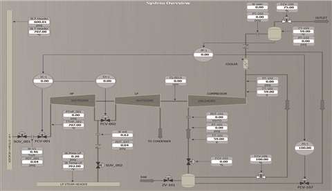 Figure 1: Single-extraction steam turbine-driven centrifugal compressor train
Train start – initially the compressor is unloaded with the SC-1 in “Local”, the EX-1 disabled, PF-1 in “Tracking” and the AS-1 in “Shutdown”. The SC-1 must be “Reset” before giving the “Start” command. This should cause the SC-1 state to change from “Shutdown” to “Ready” when all start permissives are satisfied, and no emergency shutdown signals are present.
Figure 2 shows the steam turbine after passing through the startup sequence (open-loop control). The SC-1 opened V1 (FCV-001) to 17% running the steam turbine at minimum governor speed of 4525 rpm. At this point, The SC-1 enters its closed-loop control and can be put in “Remote” to receive its setpoint from the PF-1.
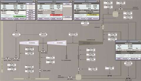 Figure 2: The steam turbine is at minimum governor and the compressor is unloaded
Compressor loading – load the compressor and adjust the setpoint for the downstream knockout drum at 660 psig [45.5 barg] (via PF-1). During loading, the AS-1 will ramp the anti-surge valve (FCV-107) close and the SC-1 will further ramp V1 open from 17 percent to 48% to satisfy the new process goal as shown in Figure 3. During closed-loop control, the SC-1 will manipulate V1 so the train’s speed is between minimum (4525 rpm) and maximum (6500 rpm) governor speeds.
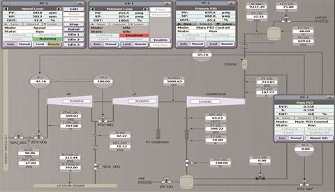 Figure 3: The compressor is loaded
Decrease in process demand while extraction is disabled – Let us step downstream valve FCV-105 close from 75% to 65% as a decrease in process demand. This will increase the knockout drum pressure above its setpoint (660 psig [45.5 barg]). The PF-1 will lower its output (remote setpoint to the SC-1), causing the SC-1 to close V1 from 48% to 40% to maintain the new process conditions shown in Figure 4.
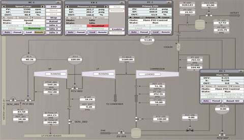 Figure 4: Reducing process demand while extraction is disabled
Enabling extraction – To maintain the low-pressure steam header at a specific pressure (initially at 215 psig [14.8 barg]), we can enable the XIC. Doing so will cause the XIC to ramp close V2 (FCV-002) from 100% to 84%, while the SC-1 will ramp open V1 from 40% to 44%, maintaining the load requirements shown in Figure 5.
 Figure 5: Enabling extraction
Increasing the process demand while extraction is enabled – Let us step the FCV-105 downstream valve open from 65% to 75% as an increase in process demand. The knockout drum pressure PT-103 will drop causing the PF-1 to increase its remote setpoint to the SC-1. This will cause V1 to further open from 44% to 48% to increase the train’s speed and build up the knockout drum pressure back to 660 psig (45.5 barg).
As a result of increasing the train’s speed, low-pressure header pressure will also increase which will request the EX-1 to ramp V2 open to maintain low-pressure header pressure at its setpoint of 215 psig (14.8 barg) as shown in Figure 6. The EX-1 will not be able to further maintain low-pressure header pressure since V2 was forced to fully open. Note that V1 and V2 worked in the same direction.
The output of the SC-1 is added to the output of the EX-1 based on load demand increase. The amount of V2 additional opening, for a given V1 opening, depends on the relative loop decoupling coefficient (here positive sign) from the SC-1 to the EX-1.
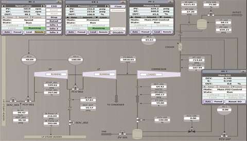 Figure 6: Increasing process demand while extraction is enabled
Increasing the extraction demand – by increasing the setpoint for the EX-1 from 215 to 230 psig (14.8 to 15.9 barg) will cause the EX-1 to close V2 from 100% to 85% to increase low-pressure header pressure. Accordingly, the SC-1 will command V1 to open from 48% to 51% to maintain the knockout drum pressure at 660 psig (45.5 barg) as shown in Figure 7. Note that V1 and V2 worked in opposite directions.
The output of the EX-1 is added to the output of the SC-1 based on the extraction demand increase. The amount of V1 additional opening, for a given V2 opening, depends on the relative loop decoupling coefficient from the EX-1 to the SC-1. Utilizing loop decoupling helped the train to smoothly stabilize satisfying load and extraction demands.
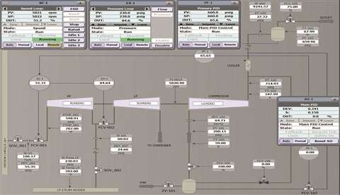 Figure 7: Increasing extraction demand
Reaction to compressor surge – as the network resistance increases, the operating point will move along the performance curve to the left to eventually reach a point of minimum stable flow and maximum pressure rise. Operating to the left of this surge limit can induce a potentially destructive phenomenon known as surge.
A surge event was generated by closing the FCV-105 downstream valve sharply from 75% to 25% as shown in Figure 8. For a well-tuned control system, the train recovered its operation after one surge cycle only as shown in Figure 9. As a result, V1 and V2 moved in the closing direction while the FCV-107 anti-surge valve opened to 26% to satisfy the new process conditions. The operator would typically rectify the FCV-105 position and then reset the surge count to eliminate recycling.
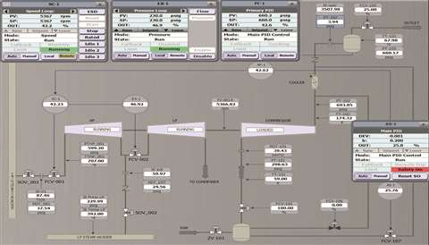 Figure 8: The train’s reaction to compressor surge
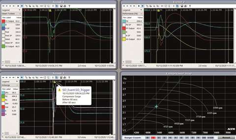 Figure 9: System trends after one surge cycle
Train stop – to safely stop the train, firstly we can disable the XIC (although it is not necessary). Next, we can unload the compressor (AS-1 will fully ramp open FCV-107). We can then put the SC-1 in “Local” so the PF-1 will track the train’s speed. This will result in running the train at its minimum governor speed as was shown in Figure 2. It is now safe to give the “Stop” command to the SC-1. A full stop sequence ramps down the steam flow through V1 until the unit slows to its minimum control speed, then shuts it down as shown in Figure 1.
Why a steam turbine-driven centrifugal compressor train should absorb upsets
To achieve integrated control of a turbine-driven rotating equipment train, various CCC controllers were developed. A well-tuned, single-extraction, steam turbine-driven centrifugal compressor train should absorb upsets and changes in process conditions, load and extraction demands.
Utilizing loop-decoupling with appropriate coefficients can further minimize process oscillations. Other application-specific features like process limits, speed priority, extraction priority and speed on V2 can be applied as needed. This should serve in smoothly running the train within its desired design boundaries.
References
Saul Mirsky, et el., “Development and Design of Antisurge and Performance Control Systems for Centrifugal Compressors”, Proceedings of the Forty-Second Turbomachinery Symposium October 1-3, 2012, Houston, Texas, USA.
Compressor Controls Corporation (CCC); UM5400, UM6431, UM6432 Reference Manuals, Mach. 2019.
STAY CONNECTED

Receive the information you need when you need it through our world-leading magazines, newsletters and daily briefings.
POWER SOURCING GUIDE
The trusted reference and buyer’s guide for 83 years
The original “desktop search engine,” guiding nearly 10,000 users in more than 90 countries it is the primary reference for specifications and details on all the components that go into engine systems.
Visit Now
CONNECT WITH THE TEAM