New Valve Wear Test Rig
09 May 2017
Editor’s Note: Results of valve wear testing were presented in a paper at the 28th CIMAC World Congress 2016 in Helsinki, Finland.
BY OLIVER LEHMANN, director of Research and Development at Märkisches Werk GmbH
German valve manufacturer Märkisches Werk estimated that valve wear according to the state of the art for large bore diesel engines is about 0.5 mm after 24 000 operating hours; in other words a wear rate of about 21 nm/h.
In contrast to large diesel engines, approximately 30 times greater wear rates (about
600 nm/h) were measured on worn inlet and exhaust valves in highly efficient lean-burn large bore gas engines, although state-of-the-art materials and proven valve designs were employed.
According to Märkisches Werk, the technical evolution of large bore gas engines to achieve higher efficiency and to cover environmental legislation as well as to lower total cost of ownership, has revealed previously unknown limits of materials, designs or manufacturing processes. Valve wear is an example that links the global tightening of emission legislations and the striving for more efficiency.
That means newly employed technical measures such as rapid burn combustion processes, lean-burn concepts, two-stage turbocharging systems and novel engine design approaches, change the operation conditions. An almost constant increase of peak combustion pressures (PCP) – higher than 250 bar in current large bore gas engines – have arisen from the dramatic changes in the combustions residues and mechanical component loads. As a result, valve wear can be clearly stated due to a lack of a protective anti-wear layer on the valve seating faces.
In the last decades, elimination of the lead and sulfur from the fuels, as well as the restriction of particle matters – which all possess anti-wear properties – have clearly aggravated the valve wear subject.
All these factors push the common valve materials to their performance limits. Also, quick-fix measures are not able to cope with this new technical challenge. Consequently, there is a need of sustainable solutions based on an extensive root cause analysis, which implies that the fundamentals of the wear mechanisms need to be understood.
Märkisches Werk decided for the set-up of a novel test rig to deeply investigate the effect of temperature, valve closing velocity, peak combustion pressure and different atmospheres on valve wear. For the first time, this test rig allows to examine the effects of these factors separately, which is not possible in a real engine. In terms of the usable valve dimensions, this newly designed setup is the world`s largest valve wear test rig, according to Märkisches Werk. However, in order to validate if the new test rig would give results representative for the actual valve wear, examinations on used valve spindles from engine tests were carried out in advance.
To quantify the valve wear, the wear scar width was measured using 3D-laser scan profilometry. In order to determine the high-resolution oxygen penetration, X-ray photoelectron spectroscopy (XPS) was employed. The oxygen penetration indicates to what an extent a valve has been subjected to wear.
Examined inlet and exhaust valves are commonly used valve spindles; bi-metal friction welded valves (valve disc diameter of about 110 mm, total length of about 550 mm) consisting of a martensitic and an austenitic stainless valve steel with hardfacing. The valves were taken from the same type of large bore gas engine.
The first set was hardfaced with a Stellite 12 alloy and was removed from the engine after 250 hours of operation, while the second set was overlaid with a Tribaloy T400 alloy and was removed after 5000 hours of operation.
The most prominent difference of the valves is the wear shown in the depth profiles and indicated in Fig. 1 and 2.


Whereas the Stellite 12 valves suffer from high wear (about 150 µm for inlet and 860 µm for exhaust) after 250 hours, the Tribaloy T400 valves show wear in the range of 20 to 30 µm after 5000 hours of operation. The operation conditions that have been prevailed during the 250 hours and 5000 hours of operation respectively allow for a fair comparison. Investigations show that no protective anti-wear layer was formed on the valve sealing interfaces.
Comparison of the microstructures below the worn valve seating faces gives hints to the reasons for different wear rates between the different hardfaced layers. Stellite 12 hardfacing shows material flow as a result of plastic damage. Plastic damage means that a permanent change has taken place, in contrast with elastic deformation. Tribaloy T400 hardfaced valves have visible hard phase cracks resulting from mechanical loading, but no plastic damage of the material could be observed, see Fig. 4.


The oxygen content of the Stellite 12 exhaust valve differed significantly from that of the inlet valve. The inlet valve shows a drop from 25 at% to less than 5 at% over 1 µm, whereas the exhaust valve shows high oxygen content above 35 at% that decreases slightly to 20 at% in 3 µm depth. This proves a high oxidation of the material which can be accounted to the higher temperature compared to the inlet valve.
The results presented thus far can be interpreted in several ways. Two different hardfacing alloys apparently lead to different wear responses. Thereby, it is difficult to explain the results directly when not all parameters during operation can be varied at liberty. Ultimately, there is the need to clarify whether the valve wear is caused by high peak cylinder pressures, aggressive atmospheres, valve closure impact, misalignment or high temperatures.
It is precisely for these reasons that Märkisches Werk developed a new test rig to provide application-relevant testing conditions for large bore gas engines in combination with full control of the discrete parameters. The test rig is an empowering tool to answer the key questions on what the wear-relevant mechanisms are for valve wear in present large bore gas engines.
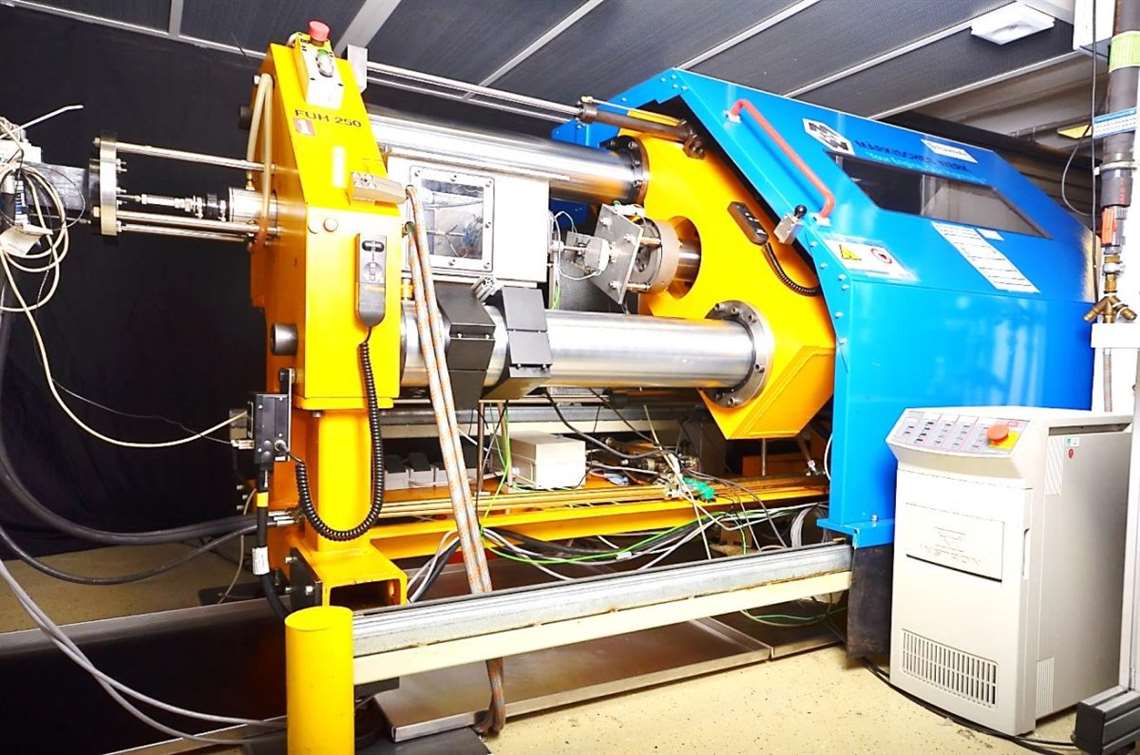
The valve wear test rig is designed as a tribometer to simulate population-relevant large bore engine valves. The rig was built up on a very stiff structure-based test frame. As sample a valve was chosen with a common disc diameter of about 90 mm and a stem diameter of about 17 mm. The possibility for a controlled variation of all test parameters offered the greatest challenge during the design process. Beside the wear-related behavior of the peak cylinder pressure and valve closing velocity (typical curves shown in Fig. 6), the impact of temperature as well as atmosphere can be studied in detail.

The inner atmosphere in the test chamber should resemble the relevant conditions inside an engine. Therefore, individual atmospheres like ambient air, nitrogen, carbon dioxide or water vapor can be employed to image the working medium in the engine. To keep a constant temperature of the components, three cooling circuits are used; two water circuits and one oil circuit.
On each component, three thermocouples are applied to monitor and control the temperature of both valve and seat ring in real time, whereas the signal cables of the valve are passed by a hollow shaft to a slip ring transmitter. A force transducer is mounted between the seat ring holder and the test frame to allow in-situ measurements of the impact forces. The valve lift can be varied by the hydraulic cylinder. The typical valve lift applied is 25 mm. A peak combustion pressure of up to 220 bar can be simulated at a valve disc diameter of about 90 mm and at a frequency of 8.6 Hz (equal to 1000 r/min). Valve temperatures up to 900° C can be reached by the heating system.
To investigate the correlation of wear behavior and load parameters, the valve spindles can be tested at various temperatures, atmospheres and valve closing velocities. In the first phase, inlet valves were examined. The test temperatures range from room temperature up to 430 °C. The closing velocity is controlled by the movement of the hydraulic cylinder and was set to 0.2, 0.6 and 1.2 m/s. Lifetimes of valves in large bore engines are normally several thousand hours. As known, properly working valve/seat ring pairs show a steady state of wear after running-in. With regard to efficient testing and to comply with large bore engine applications, a testing time of 100 hours was defined.
Testing at a material temperature of ambient value showed almost no wear, as shown in Fig. 7.

The explanation is that the material has a high strength at such a temperature. At a material temperature of 380 °C, the wear rate was already a factor of 20 higher. Further increasing of the material temperature to 450 °C and doubling the valve closing velocity resulted in a factor of about 60 higher than that at ambient conditions.
In conclusion, the investigation by Maerkisches Werk of worn valves made of two different hardfacing alloys that are commercially available and widely used for valves and seat rings in large bore engines applications found that Stellite 12 hardfacings tend to be stronger plastically damaged than Tribaloy T400. Furthermore, the surrounding atmosphere reacts with the hot material surfaces during operation, leading to formation of oxides as well as oxygen penetration.
From the comparison of the engine tests with the lab-scale experiments, the measured linear wear rate of 2.2 µm/h as found with the test rig is of the same magnitude as for the severely worn valves of about 3.6 µm/h from real engine test. Hence the test rig has proven that it is able to produce wear rates equal to those found in real engine tests.
Consequently, this rest rig established a valuable research tool for the study of wear mechanisms of valve closure and peak cylinder pressure of highly efficient large bore gas engines in detail in a laboratory environment. This opens up possibilities for a reliable and fast development of intake and exhaust valves as well as seat rings suitable for application in modern high-performance large bore gas engines.
STAY CONNECTED

Receive the information you need when you need it through our world-leading magazines, newsletters and daily briefings.
POWER SOURCING GUIDE
The trusted reference and buyer’s guide for 83 years
The original “desktop search engine,” guiding nearly 10,000 users in more than 90 countries it is the primary reference for specifications and details on all the components that go into engine systems.
Visit Now
CONNECT WITH THE TEAM