Turbomachinery: Laser Welding
04 April 2023
Written by Michael W. Kuper, PhD., Materials Engineer, Elliott Group and Michael J. Metzmaier, Welding Engineer IV, Materials Engineering, Elliott Group
Laser cladding is gaining acceptance for restoration of turbine and compressor shafts, which has resulted in increased customer demand for laser cladding options, and an increased number of laser welding suppliers who are offering a variety of solutions.
Therefore, it is important to understand the basic capabilities, limitations, and potential pitfalls of the laser cladding process, and how the process should be qualified to ensure that laser weld repairs meet requirements for the given application.
As with any welding process, the desired outcome is a metallurgically sound deposit that meets or exceeds the minimum application design criteria. Filler material alloy selection, form, and delivery methods can have a significant impact on the quality and suitability of the weld deposit.
One of the most critical components of turbomachinery equipment is the rotor. These precision assemblies rotate at extremely high speeds and must withstand significant stresses for extensive service times.
To achieve this level of reliability, manufacturers must ensure that the components are suitable for the application. Tight controls on composition, mechanical properties, and processing ensure that the parts are acceptable.
These inspections, verifications, and safeguards maximize the usable service life while minimizing the risk of catastrophic failure.
However, wear and tear from normal operation will eventually cause sufficient damage that requires repair or replacement. Accumulated damage is generally superficial, and repair offers a cost and time advantage, as compared to replacing the entire rotor, while adding minimal risk related to the repair process.
Typical repair processes include spray coating, plating, arc welding, plasma welding, and laser welding. Each of these processes has advantages and disadvantages, depending on a variety of factors, including the location and extent of damage, operating conditions, service environment, the substrate and desired repair material, and customer acceptance.
This article focuses specifically on laser welding repairs and how the laser welding process can be beneficial for compressor and turbine shaft repairs, including considerations to be addressed.
The discussion includes the most commonly repaired shaft areas, the risks associated with laser welding in these locations, and the types of tests that should be required to qualify the procedure.
Laser Beam Welding
Before the advent of laser beam welding (LBW), the most common process for shaft repair was submerged arc welding (SAW), mainly because the process is robust and offers a high deposition rate.
However, this process involves high heat input, which can cause distortion of the shaft and high residual stress. Because of distortion, SAW repairs tend to require removal of all protruding features from the repair area, rebuilding of those features, and extensive overlaying to ensure sufficient machining stock to restore dimensions.
Also, because of the high residual stress from welding, repairs always require a post weld heat treatment (PWHT) before final machining, which relieves residual stresses that minimize shaft movement (distortion) during the machining operation.
Access to a focused laser allows for welding (including cladding), cutting, and heat treatment. Although LBW has existed since the 1970s, improvements in technology and affordability have expanded its range of industrial applications which now include turbomachinery rotor restoration.
The main advantage of LBW is that it is a high energy density process, and is therefore capable of welding with very low heat input, which minimizes base metal degradation, the size of the heat affected zone (HAZ), residual stress, and distortion, while also enabling very fast welding speeds.
Meanwhile, the smaller HAZ is also beneficial in that less of the shaft volume has the potential for detrimental properties caused by the heat from the fusion process.
This is particularly important in the case of heat treatable alloys such as quenched and tempered steels, which are commonly used for turbomachinery rotors. An example laser welding setup is shown in Figure 1.
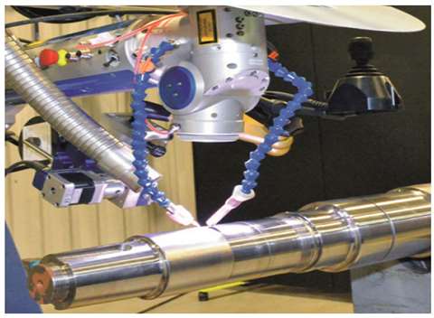 Figure 1. Laser Welding Setup. (Photo: Elliott Group.)
In addition to low heat input, the LBW process produces high quality fusion welds with a metallurgical bond (no delamination, which can occur in coatings based on adhesion), is easily automated for consistency and repeatability, and has high geometric precision.
For example, the spot size of the laser used for this study can range from 0.2 mm in diameter for small welds, to 2.0 mm in diameter for higher deposition rate overlays.
To capitalize on the advantages of the LBW process, the process capabilities must be matched with the application, and additional considerations, outlined below, must be explored before implementing LBW for rotor restoration.
Filler Metal Delivery
There are two distinct laser welding processes. One uses powder-based filler metal (LBW-P), and one that uses wire-based filler metal (LBW-W). In LBW-P, powder is delivered from a powder feeder through tubing and one or more nozzles by a jet of inert gas, which delivers the powder into the weld pool.
In LBW-W, the filler metal is delivered by feeding the wire into the weld pool, either by hand or by a mechanized wire feeder.
These two methods have metallurgical as well as logistical differences that must be considered when determining the most appropriate process for a given repair. This is especially true considering that these differences are not yet accounted for in ASME BPVC.
Variables for welding procedure specifications (WPS) for laser beam welding are covered by ASME BPVC Section IX Table QW-264 and QW-264.1.
Among the essential variables are specifics related to the powder filler metals, including powder metal size, density, and feed rate. However, there is no mention of filler wire parameters.
This indicates that the current code only considers powder-based laser welding applications. It follows that procedure qualification would then also only be relevant for powder based laser welding.
This is one reason why additional procedure qualification requirements may be necessary for laser beam welding.
The Laser Source
A variety of laser sources can be used for laser welding. This article focuses on two of the most common laser sources for welding on Nd:YAG lasers and fiber lasers.
Nd:YAG lasers consist of a neodymium doped yttrium aluminum garnet crystal that is excited by a xenon flashlamp to produce the laser beam, while fiber lasers consist of an array of diodes that excite an optical fiber doped with rare earth elements to produce the laser beam.
While either of these laser sources can be used for rotor restoration, each of them offers tradeoffs, including beam quality, beam size, beam frequency, lifespan, cost, and efficiency.
Choosing the best laser depends on the application. When ASME BPVC compliance is a concern, however, the fiber laser is the better choice.
The reason for this is the difference in the way that the laser beam is generated, and its stability over time. Within the Nd:YAG laser, the xenon flashlamp bulb degrades over time and becomes dimmer as it ages.
The dimmer bulb results in lesser excitation of the Nd:YAG crystal, which decreases the intensity of the laser beam produced. The effect is that the power output for a given laser setting decreases throughout the lifetime of the flashlamp, though the rate of degradation will likely be unknown.
This is problematic for compliance, since according to ASME BPVC Section IX Table QW-264, laser power is a critical variable that may not be changed for a given weld procedure.
Maintaining this requirement would be nearly impossible for an Nd:YAG laser, although this fact is not mentioned in the code. In contrast to Nd:YAG sources, fiber laser sources do not have this problem, since excitation is performed by diodes.
Therefore, fiber lasers are vastly superior, and arguably necessary, in situations that require code compliance.
Continuous or Pulsed Laser
Some laser systems now have the ability to operate in both a pulsed mode and a continuous operating mode. The advantage of using a pulsed laser is that the heat input can be reduced to minimize the size of the HAZ, the amount of residual stress, and the amount of distortion.
Aside from the general advantages, pulsing is also useful in specific instances, such as welding on a finish-machined part, where a PWHT is not possible. This is because pulsed power has a lower heat input than continuous power.
Pulsed laser operation, however, is mostly limited to LBW-W, as LBW-P systems operate most effectively using continuous power. This is because in powder-based applications, the powder is delivered continuously, which would result in a large amount of wasted powder or lack of fusion caused by insufficient heat between pulses.
For wire-based systems, the wire feeder is precisely controlled by the equipment to maintain stable welding conditions. It is worth noting that weld mode as a standalone variable can also have an effect on the deposition rates of the welding process, but this is largely dependent on the type of system, as well as the conditions of the repair.
Overall, the weld mode should be chosen based on the type of filler metal delivery, but also based on the type of repair and desired weld properties.
Joint Design
To minimize the potential for defects, the joint design must be suitable for the type of welding system used. Wire-based welding systems are typically more tolerant of sharp corners and deep grooves than powder systems.
This is due to the fact that wire systems do not require a gas transport system to deliver the filler material to the weld zone. In powder-based welding systems, turbulence in the carrier gas used to deliver powder to the melt pool caused by the substrate geometry, such as a v-groove, can lead to poor powder delivery rates and poor shielding.
Poor powder delivery rates result in low welding efficiency and excess heat reaching the substrate, while poor shielding can result in porosity and the formation of oxide inclusions. Additionally, for LBW-P, excess unfused powder can accumulate in the joint as well.
Welding over this loose powder can cause significant defects, including lack of fusion, porosity, or cracking. As a result, powder based filler metal delivery in a groove requires a wider groove angle, which creates more access to the weld joint, but also increases the volume of the groove.
Therefore, the volume of the v-groove necessary for extracting test specimens when using LBW-P is very large compared with the typical size of a laser weld bead, making the manufacture of test specimens for procedure qualification impractical.
In the case of wire-based filler metal delivery, the angled wall of the groove creates geometric challenges for shielding gas and wire delivery, which increases the likelihood of porosity and increases the susceptibility for lack of fusion defects.
However, groove welding is possible with LBW. Additionally, for most shaft repairs where LBW is applicable, the repairs tend to be weld overlays, which do not require groove welding.
Figure 2 shows common shaft repair types including overlays, buildups, and stub repair. Although stub repair would require groove welding, it would not generally be performed using LBW, since other processes have a higher deposition rate.
Regarding filler material type, LBW-P and LBW-W will be acceptable for general shaft repairs, though caution should be taken when welds will be close to steps or features that could cause turbulence with a powder process.
However, weld procedure qualification requirements may be impossible or impractical for LBW-P, and LBW-P may also struggle where porosity is unacceptable.
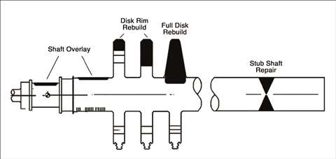 Figure 2. Common shaft repairs
Filler Metal Cost and Availability
The ability to choose a filler metal is dependent on the availability of the material in question.
Generally, both wire and powder versions are available for a variety of materials.
However, wire-based materials tend to be limited to commonly welded alloys, while powder materials tend to be geared toward higher alloy steels and specialty alloys.
This is because one of the key drivers for powder production is powder-based additive manufacturing, which has the highest cost-benefit ratio for the more exotic materials.
Because of this, it is difficult to find carbon and low-alloy steel in powder form, since these materials are cheap enough that the use of powder form is not cost effective for most industrial applications.
Since carbon and low alloy steels are used heavily in the turbomachinery industry, wire-based laser welding systems tend to be a better option due to better availability of these materials. Additionally, filler metal in wire form is also generally less expensive than powder form.
Defects
From an applications standpoint, one major difference between powder-based and wire-based laser welding is the type of defects and the likelihood of forming defects during welding.
LBW-W is capable of producing fully dense, defect-free welds, while LBW-P usually has a small amount of porosity at a minimum. Regardless, suboptimal welding parameters, joint geometry, or conditions can generate defects for either process.
Typical defects that occur in laser welding include the following, with examples shown in Figure 3, which shows defects in an LBW-P overlay.
- Porosity
- Lack of fusion
- Unfused particles
- Cracking
Porosity is characterized by voids that occur within the weld deposit, created by escaping gases that become trapped during solidification.
For LBW, there are several methods by which gasses can be introduced into the weld pool, but the main theories include trapping shielding gas or metal vapors, cavitation caused by unstable keyhole welding, and gasses that were entrapped in the powder particles during the atomization process and released during welding.
In addition, porosity can occur from poor shielding gas coverage during welding, which is usually caused by an improperly aligned gas lens or turbulence near the weld pool.
This may occur because of the turbulence created by rapid oxidation of the solidifying weld pool, or from gasses created from burning the oxygen found in air. Lastly, lack of base metal and filler material cleanliness can also contribute to porosity.
Welding over organic matter (oil, grease, dirt, oxides, etc.) causes outgassing during welding that becomes trapped in the weld pool as it solidifies.
Lack of fusion is characterized by locations where the filler metal did not fuse with the base metal. This occurs when the heat source generates insufficient heat to coalesce the filler and base metals.
The typical causes for this include poor welding angle, excessive filler material feed rate, and/or inadequate laser power. Similar to lack of fusion, unfused particles are characterized by remnants of unmelted powder being present in the weld.
This type of defect is exclusive to LBW-P because it involves powder while LBW-W does not. The cause of unfused particles is similar to lack of fusion, where there is insufficient heat to fully melt and fuse the filler material with the base material.
 Figure 3. Typical Defects that Occur in Laser Welding. These defects were found in a weld made using powder based filler metal delivery. Porosity can be seen speckling each image.
This generally occurs because the laser did not have the time, power, and/or correct positioning to melt all of the filler metal in the weld area.
Cracking is characterized by weld metal fracture because of stress. Cracking can be caused by a multitude of factors, though common examples include highly restrained joint design, rapid cooling rates, filler metal susceptibility, contamination, weld bead profile, and/or incorrect welding parameters.
About the authors
Dr. Michael W. Kuper is a materials engineer in the Product and Technology Group at Elliott Group. He has a B.A., an M.S., and a Ph.D. in Materials Science and Engineering from the Ohio State University.
His past experiences include analysis of dissimilar metal welds involving 9Cr-1Mo-V steel welded with nickel based filler metals, and high deposition rate additive manufacturing of metallic materials.
He currently has 5 publications, has presented research at more than a dozen technical conferences, and is an active peer reviewer for the journal Welding In the World.
Michael Metzmaier is a welding engineer in the Materials Engineering Department at Elliott Group. He has a B.S. in Welding and Fabrication Engineering Technology from the Pennsylvania College of Technology.
He has held various positions within Elliott Group includling manufacturing engineer, rotor division supervisor, and welding engineer.
STAY CONNECTED

Receive the information you need when you need it through our world-leading magazines, newsletters and daily briefings.
POWER SOURCING GUIDE
The trusted reference and buyer’s guide for 83 years
The original “desktop search engine,” guiding nearly 10,000 users in more than 90 countries it is the primary reference for specifications and details on all the components that go into engine systems.
Visit Now
CONNECT WITH THE TEAM