Imes updates engine analyzer

03 February 2022
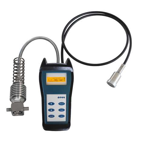
Imes said its EPM-XPplus engine analyzer now offers the possibility of additional vibration measurements on marine engines.
A vibration sensor was specifically developed by IMES that is electrically connected on one side to the hand-held device via a cable and on the other side via a magnetic holder to the injector or pump. The subsequent evaluation of the measured data will be processed by the EPM-XPplus visualization software.
By regular measurements during engine operation with the EPM-XPplus without vibration sensor the engineer can detect occurrent failure. Possible causes of failure could be a deviation from the mean indicated pressure (MIP), the peak pressure (Pmax) or compression pressure (Pcomp). The failure can be immediately identified by the analysis of the indicator diagrams. However, there are a number of effects that are very hard to identify only by analyzing the indicator diagrams, especially failure at the high-pressure fuel system and failure at the control of the inlet valve and exhaust valve.
With the existing procedure of the cylinder pressure indicator system, the exact point of fuel injection and the valve movement cannot be determined or only inexactly determined. A direct measurement of these processes is very extensive.
The vibration sensor as part of the engine analyzer EPM-XPplus offers advanced diagnostic options for marine engines. For direct measurement the vibration sensor will be e.g., magnetically installed on the injector. During cylinder pressure indication the vibration sensor records the point of lifting and landing of the injector needle as well as the beginning and ending of the fuel supply by the injection pump.
The experience in the performance analysis of marine engines shows, that the analysis of vibration diagrams, that have been recorded parallel to the indicator diagrams, delivers very good results.
Marine engineers can achieve the following results by using the EPM-XPplus device including vibration sensor:
- Phases of lifting and landing of the injector needle
- Beginning and ending of the circulation of the heated heavy fuel in the fuel system
- Phases of beginning of fuel supply and of shutdown of the high pressure pump
- Phases of closing and in some cases of opening of the gas distribution valves
The user will get all this information directly during operation with the vibration sensor. This method described above also fulfills the requirements of the marine classification societies regarding non-destructive application as there is no need for mechanical intervention at the engine for installing the vibration sensor.
STAY CONNECTED

Receive the information you need when you need it through our world-leading magazines, newsletters and daily briefings.
POWER SOURCING GUIDE
The trusted reference and buyer’s guide for 83 years
The original “desktop search engine,” guiding nearly 10,000 users in more than 90 countries it is the primary reference for specifications and details on all the components that go into engine systems.
Visit Now
CONNECT WITH THE TEAM