Picking The Right Excitation System
26 July 2023
Generator set manufacturers offer different options for providing power to the automatic voltage regulator (AVR) – Self-Excited (or Shunt), Excitation Boost System (EBS), Permanent Magnet Generator (PMG) and Auxiliary Winding (AUX). Selecting the proper option is important to ensure the correct operation of the generator set.
In a generator system, AVR voltage sense lines are connected to the main stator and provide feedback to the AVR in order for the AVR to control the field strength of the alternator and maintain a constant output voltage for the generator set under varying conditions. Input power is used by the AVR to supply a dc output to the exciter stator and voltage level sensing is used to determine the level at which the AVR induces an ac signal on the exciter rotor. The exciter rotor’s ac output is then rectified to a dc output into the main rotor of the alternator and ultimately induced onto the main stator for load output.
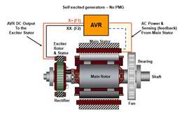 Shunt Excitation. (Source: Cummins)
For this process to work, the AVR must have a power source that will allow for the appropriate amount of excitation current when needed, especially in transient situations. Lacking sustainable power, the system may be unable to recover voltage during a motor start or fault condition, which could lead to the motor struggling to start or resulting in shutdown due to loss of field in the alternator.
AVRs can incorporate constructions that impact their ability to provide appropriate excitation based on the voltage sensing and power input. Two types of AVR are Silicone-Control-Rectifier (SCR) and Field-Effect Transistor (FET). Each type can have an impact on system performance in conjunction with the excitation type.
Shunt, or self-excited excitation, uses the output of the main stator to derive power for the input to the AVR. This same output is used for sensing the alternator output to continue properly regulating the voltage required to the exciter. This is a very simple and cost-effective approach to providing the input power the AVR needs to properly excite the alternator and it requires no additional parts or wiring and can allow for easier troubleshooting.
The simplicity of Shunt excitation also leads to its biggest drawback since the input power quality to the AVR is directly impacted by the loads the alternator is powering downstream. When a transient occurs due to a load connecting/starting or a fault appears downstream, the voltage and frequency will drop and the AVR must drive more excitation current to support the voltage. With reduced input voltage, powering the AVR can become a challenge, especially in the case of a short circuit fault where the voltage collapses. In that case, the AVR will not have the capability to support the voltage long enough to clear downstream faults as the main field in the alternator may collapse.
In other words, if the voltage reaches zero before downstream faults have been cleared (breakers tripped), the field will collapse. The self/shunt-excited machines require sizing of protective equipment (breakers) that will respond within two seconds (typically, 100-120 cycles), as that is the time it takes for the field to collapse (all collected energy within the stator to be dissipated).
Harmonics caused by powering non-linear loads can also be a challenge for a shunt excitation system, as the power input variation can affect the ability of the AVR to provide appropriate output power, as the harmonic distortion may impact the behavior of the power circuit within the AVR.
 Source: Cummins
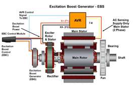
EBS excitation
The Excitation Boost System (EBS) is another excitation type that provides a “boost” to the typical self-excited system. The construction of this system follows the same setup of the shunt excitation for voltage sensing and power input to the AVR and also includes an excitation boost control (EBC) module and a small excitation boost generator (EBG) added to the non-drive end of the alternator shaft. The EBC module is connected to the AVR and provides the ability to directly engage varying levels of increased excitation current depending on the needs of the system.
The additional power output from the EBG is in parallel with the typical AVR exciter output lines and is engaged by the AVR as needed through a command to the EBC. This power feeds the generator’s excitation system for a limited time, supporting the load until a downstream breaker can remove a fault or enable the generator to pick up a motor and drive the voltage recovery. While similar in appearance to a permanent magnet generator (PMG) excitation system, the EBG is not rated for continuous power output to the AVR, but rather is suitable for shorter output situations. During generator startup, the EBS is off to prevent excessive voltage runup. It produces a voltage potential but not excitation.
The construction of the EBS system is different from a PMG in that it allows for a dynamic response in motor starting and short circuit situations. With the EBG being rated for non-continuous usage, it is a less expensive and smaller option that still meets the needs of providing 300% short circuit current and improved motor starting.
 Source: Cummins
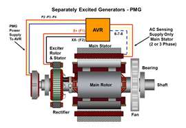
PMG excitation
The separately excited or permanent magnet generator (PMG) is the most common excitation system for applications with high-performance requirements for motor starting, selective coordination and non-linear loads. PMG systems utilize an additional small permanent magnet generator at the non-drive end of the alternator to produce power for the AVR. This PMG output is isolated from the disturbances on the main output from the alternator and produces an uninterrupted three-phase waveform as long as the alternator shaft is turning, thereby preventing any disturbances to the input power of the AVR. It provides reliable isolated power to the AVR where significant voltage waveform distortion may have been a problem in a self-excited system.
PMG excitation offers a number of benefits for both motor starting and non-linear loading situations. These include:
- It provides sustained short circuit (SSC) current during fault conditions which prevents the field from collapsing and allows for faults downstream to clear.
- Non-linear loads have no impact on the ability to provide power to the exciter.
- It provides powerful voltage buildup on initial startup rather than relying on residual magnetism.
- It provides isolation from high transient conditions in motor starting situations which otherwise would limit the AVR in its ability to provide full excitation to recover voltage and ultimately torque for the motor to get up to speed quickly.
AUX excitation
Auxiliary winding excitation (AUX) has been used for many years on marine and industrial applications. While less common, it is not a new technology and is seen as more practical in larger installations.
 Source: Cummins
AUX excitation uses the main field to generate power for the AVR through a separate single-phase winding that is inserted into the main stator alongside the main output winding. This configuration eliminates the need for a separate PMG on the end of the alternator and avoids the issues Shunt can have with sustainable power output and harmonics due to non-linear loads. However, the physical space that the Auxiliary winding occupies means less available slot space for main windings, and therefore in some cases can present a challenge to construction of the machine, as well as reduce the power capability relative to the same machine without an Auxiliary winding.
A benefit of the AUX winding is that it results in a shorter axial length of the generator set and reduced production costs, as there is less equipment to install compared with PMG systems. While its voltage input to the AVR can be affected to a certain extent by the power being generated, it has a negligible impact on the performance of the set. It also provides a very robust solution with low failure rates. By design, the mutual inductance with the main winding is minimized and the waveform distortions in the main winding from non-linear loads will not affect AVR performance.
Both PMG and the AUX winding are suitable options for demanding applications.
AVR construction
The type of AVR – Silicone-Control-Rectifier (SCR) or Field-Effect Transistor (FET) – can have a significant impact on the ability of each type of excitation circuit. Both SCR and FET systems have independent input power and voltage sense circuits in which the voltage sense lines are pulled from the main stator which can result in a distorted voltage feedback signal from harmonics caused by customer connected loads. How each system deals with the power circuit and voltage sense lines is important to generator set performance.
 AUX winding excitation. (Source: Cummins)
SCR AVR systems sense the voltage level on the output of the alternator, using that level to time the firing of the SCR. It determines both when the switch is to be turned on and off. The voltage level is used as a feedback loop to determine when the switch should be turned on and the switch will turn off based on when the voltage waveform reaches zero, also called zero-crossing. The length of time the switch is on determines the amount of power being sent to the exciter.
It also uses the zero-crossings on these lines to determine the system frequency when a magnetic pickup is not used. This impacts the timing of the SCR firing and may be used to adjust the electronic governor within the AVR. This can be especially troubling with non-linear loads as the harmonic distortion and induced “notches” can cause additional zero-crossing points, which cause the system to struggle to deliver the appropriate amount of excitation. It can also cause improper frequency sensing.
For these reasons, an SCR-type AVR is not recommended for large amounts of non-linear load with Shunt or EBS excitation systems. The use of PMG or AUX will be an improvement due to cleaner input power, so there will be no improper zero-crossings causing the SCR to shut off early. However, the voltage sense lines will still be problematic with a distorted voltage as the zero-crossings will still drive improper excitation and inaccurate frequency readings if no mag pick-up is used.
FET AVR
The FET-type AVR system has many advantages that are suited for all four excitation systems for improved performance when relating to non-linear loads and potential distortion. In the case of the FET AVR, the voltage sense lines are measured and translated to drive a pulse width modulated (PWM) circuit for the excitation output. The translated signal dictates the duty cycle of the PWM signal and, ultimately, the amount of excitation being applied. This method prevents zero-crossings from dictating a single event or notch from impacting the amount of excitation by constantly pulsing and adjusting the duty cycle. The power input waveform is only used for excitation output and is filtered and rectified to a dc signal. This also prevents the power quality from having an impact on the excitation capability of the system.
The FET-type AVR also uses a magnetic pickup and derives the frequency from this signal only, preventing false frequency information due to non-linear loads.
The effect of using a FET-type AVR with the different AVRs is significant. With a Shunt or EBS excitation system, the concerns for harmonics due to non-linear loads are mostly eliminated and with the PMG or AUX systems, the few limitations on SCR-type systems are completely eliminated.
Overall, each type of excitation system has advantages in different applications. For simple applications requiring a low-cost solution with few motors or non-linear loads, Shunt excitation may be the appropriate choice.
For the most demanding applications requiring large motor starting, improved motor starting capability, non-linear load demands, and sustained short circuit capability during large faults, PMG and AUX systems should be considered. The PMG isolates the AVR power source from the alternator output and provides reliable and constant power supply to the AVR. The AUX winding takes advantage of the inherent harmonics within the generator to reduce the size of the set while still providing strong motor starting and sustained short circuit capability.
Information for this article is from the white paper, “A Comparison of Generator Excitation Systems,” by Greg LaLiberte, global product manager at Cummins Power Generation.
STAY CONNECTED

Receive the information you need when you need it through our world-leading magazines, newsletters and daily briefings.
POWER SOURCING GUIDE
The trusted reference and buyer’s guide for 83 years
The original “desktop search engine,” guiding nearly 10,000 users in more than 90 countries it is the primary reference for specifications and details on all the components that go into engine systems.
Visit Now
CONNECT WITH THE TEAM